MENÜ

Double Pulse Testing


The Standard Method for Measuring Switching Parameters​

Minimizing switching losses continues to be a major challenge for power device engineers working on SiC and GaN devices. The standard test method for measuring switching parameters and evaluating the dynamic behavior of Si, SiC, and GaN MOSFETs and IGBTs is the double pulse Test (DPT). Double pulse testing can be used to measure energy loss during device turn-on and turn-off, as well as reverse recovery parameters.


Double Pulse Test and the Benefits


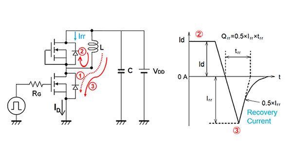
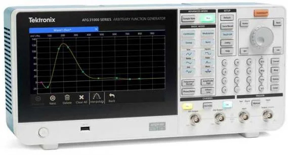
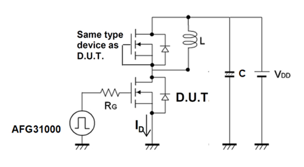
The Basics of Double Pulse Test

Performing a double pulse test is performed using two devices. One device is the device under test (DUT) and the second device is typically the same type of device as the DUT. Note the inductive load on the “high” side device. The Inductor is used to replicate circuit conditions that you may have in a converter design. The instruments used are a power supply or SMU to supply the voltage, an arbitrary function generator (AFG) to output pulses that trigger the gate of the MOSFET to turn it on to start conduction of the current, and an oscilloscope to measure the resulting waveforms.

Double Pulse Testing for Power Semiconductor Devices with an Oscilloscope
and Arbitrary Function Generator


How to Generate Gate Drive Signals for a Double Pulse Test

The easiest way to generate the gate drive signals to perform a double pulse test is to use an arbitrary waveform generator (AFG). An AFG may be used to generate the gate drive signal to perform a double pulse test. The Tektronix AFG31000 has a built-in double pulse test application to create the pulses with varying pulse widths.

Double Pulse Test with the AFG31000


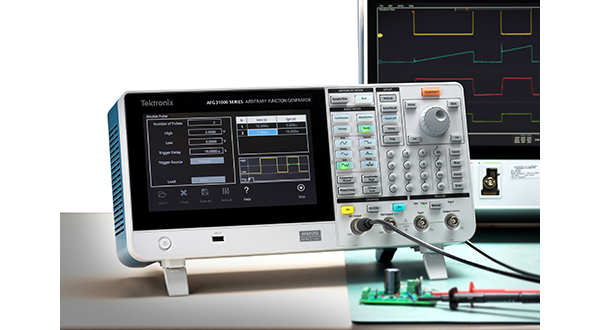
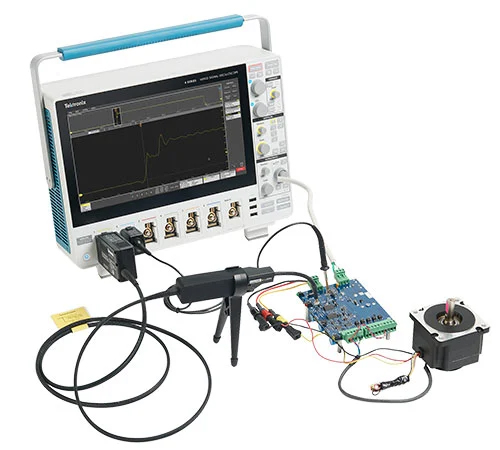
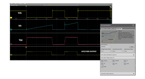
How to Measure Turn-on and Turn-off Timing
and Energy Losses

An oscilloscope is a great tool for capturing the double pulse waveforms so you may obtain the turn-on and turn-off times parameters of your device. With the Tektronix 4/5/6 Series B MSO and the Wide Bandgap Double Pulse Test application software (Opt. WBG-DPT), everything you need to capture the parameters is at your fingertips. The WBG-DPT option offers automated switching, timing, and diode reverse recovery measurements per JEDEC and IEC standards.

Double Pulse Testing - Energy Loss Measurements

4/5/5B/6B Series MSO Option 4-WBG-DPT/5-WBG-DPT/6-WBG-DPT Application Datasheet


Measure Reverse Recovery

Reverse recovery time of the diode is a measure of the switching speed in the diode
and thus affects the switching losses in the converter design. Reverse recovery current
occurs during the turn-on of the second pulse. As shown in the diagram, the diode is
conducting in a forward condition during phase 2. As the low side MOSFET turns on
again, the diode should immediately switch to a reverse blocking condition; however,
the diode will conduct in a reverse condition for a short period of time, which is known
as the reverse recovery current. This reverse recovery current is translated into energy
losses, which directly impact the efficiency of the power converter.


Products


5 Series MSO is a mixed signal oscilloscope with a high definition display with a touchscreen, up to 8 inputs, 12-bit analog-to-digital converters and bandwidth up to 2 GHz.


Troubleshoot and validate high-speed designs with bandwidth that starts at 1 GHz and goes up to 10 GHz.
x
X


Accelerate validation around SiC and GaN power devices and systems with this full suite of instruments, software, probes and services.   Increase your system performance and lower your time-to- …


The AFG31000 Series with InstaView™ technology is a high-performance function generatorwith built-in waveform generation applications, patented real-time waveform monitoring, and a modern user interface
x


Probing systems make high-resolution measurements in the presence of common mode signals or noise.
x
x
X