Giriş Yap
Ara
-
ÜRÜNLER
-
Endüstriyel ve HighTech Ürünler
- Güvenilirlik Çözümleri
- Elektriksel Test Cihazları
- Termal Kameralar
- Mekanik Ölçüm
- Multimetreler
- Pens Ampermetreler
- Laboratuvar ve Çevresel Ölçüm Cihazlari
- Elektronik Yükler
- EMC-Elektromanyetik Uyumluluk
- Termometreler
- Pico Auto
- Frekans ve Zaman Ölçerler
- Güç Kaynakları
- GPIB Arayüz Çözümleri
- Kablolama Sistemleri
- Kalibrasyon Cihazları
- Kayıt Cihazları (Recorder)
- Kaynak ve Ölçüm Sistemleri
- Komunikasyon Test Cihazları
- Konumlandırma
- Lojik Analizörler
- Mobil Kablosuz Komunikasyon Test Cihazları
- Optik Cihazlar
- Osiloskoplar
- Power Metreler / Sensörler
- Rezistans / Kapasite / Direnç / Empedans Çözümleri
- Sinyal Üreteçleri
- Spektrum Analizörler
- Vektör Network Analizörleri
- Yazılımlar
- Network Cihazlar
-
Eğitim Setleri ve Aksesuarları
- İklimlendirme & Soğutma
- Yenilenebilir Enerji
- Yüksek Gerilim
- Ağ Sistemleri
- Avionic
- Biyomedikal
- Elektrik & Elektronik, Breadboardlar ve Aksesuarlar
- EMI-EMC Ölçümleme
- Kontrol, Mekatronik ve Sensör Teknolojileri
- Mikroişlemciler
- Otomotiv
- Temel ve İleri Düzey Haberleşme
- Malzeme Test Laboratuvarı
- Nesnelerin İnterneti
- Biyomedikal Cihazlar
-
Endüstriyel ve HighTech Ürünler
- UYGULAMALAR
- KAMPANYALAR
- REFERANSLAR
- BLOG
- İLETİŞİM
 KALİBRASYON LABORATUVARI
 GaN and SiC Switching Device Measurements
 Transistor Safe Operating Area (SOA)
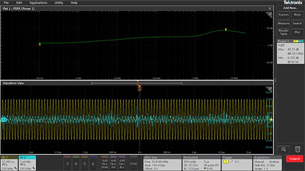 Power Supply Rejection Ratio
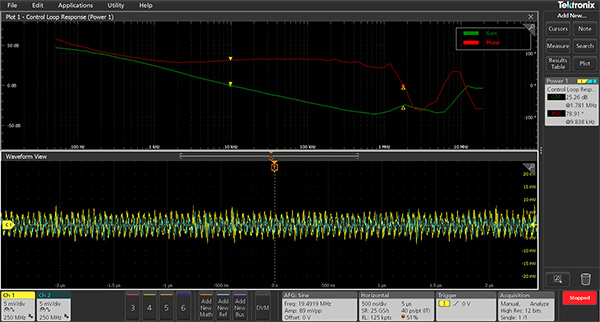 Power supply control loop